用自定义的方法关闭节点时,代码一般是这样的:1
2
3
4
5
6
7
8
9
10
11
12
13
14
15void mySigintHandler(int sig)
{
ROS_INFO("Exit from my_node !");
ros::shutdown();
ros::waitForShutdown();
}
int main(int argc, char** argv)
{
ros::init(argc, argv, "my_node", ros::init_options::NoSigintHandler);
ros::NodeHandle nh;
signal(SIGINT, mySigintHandler);
ros::spin();
return 0;
}
为什么这样做,原因看ros::start()的源码就明白了,其中有一句:1
2
3
4
5
6
7
8
9
10if (!(g_init_options & init_options::NoSigintHandler))
{
signal(SIGINT, basicSigintHandler);
}
void basicSigintHandler(int sig)
{
(void)sig;
ros::requestShutdown();
}
这就是配置ROS启动flag的问题,它是个枚举值,定义如下:1
2
3
4
5
6
7
8
9
10
11
12
13 // Flags for ROS initialization,在命名空间ros::init_options
enum InitOption
{
//不安装SIGINT handler,可以安装自定义的SIGINT handler
NoSigintHandler = 1 << 0,
// 匿名节点模式,在节点名最后添加随机数,使得可以同时运行多个同名节点
AnonymousName = 1 << 1,
// brief Don't broadcast rosconsole output to the /rosout topic
NoRosout = 1 << 2,
};
typedef init_options::InitOption InitOption;
再看上面的源码,如果ROS flag不是NoSigintHandler,那么basicSigintHandler就是默认的SIGINT回调函数,它会运行ros::requestShutdown();,所以我们在运行节点时,按Ctrl+C可以退出节点。
下面我们详细看看这个过程,先看回调函数中的函数requestShutdown,1
2
3
4void requestShutdown()
{
g_shutdown_requested = true;
}
只有一个赋值,而处理变量g_shutdown_requested的只有一个函数checkForShutdown1
2
3
4
5
6
7
8
9
10
11
12
13
14
15
16
17
18
19void checkForShutdown()
{
if (g_shutdown_requested) // 除非ros::requestShutdown()
{
// Since this gets run from within a mutex inside PollManager, we need to prevent ourselves from deadlocking with another thread that's already in the middle of shutdown()
boost::recursive_mutex::scoped_try_lock lock(g_shutting_down_mutex, boost::defer_lock);
while (!lock.try_lock() && !g_shutting_down)
{
ros::WallDuration(0.001).sleep();
}
if (!g_shutting_down) // ros::start()中赋值为false,之后未变
{
shutdown(); // 关闭节点
}
g_shutdown_requested = false;
}
}
而跟checkForShutdown有关的只有PollManager::instance()->addPollThreadListener(checkForShutdown);,它位于ros::start()中:1
2
3PollManager::instance()->addPollThreadListener(checkForShutdown);
. . . . . .
PollManager::instance()->start();
函数的定义如下:1
2
3
4
5
6
7
8
9
10
11
12
13
14
15
16
17
18
19
20
21
22
23
24
25
26
27
28
29typedef boost::signals2::signal<void(void)> VoidSignal;
VoidSignal poll_signal_;
typedef boost::function<void(void)> VoidFunc;
// 使用了观察者模式
boost::signals2::connection PollManager::addPollThreadListener(const VoidFunc& func)
{
boost::recursive_mutex::scoped_lock lock(signal_mutex_);
return poll_signal_.connect(func);
}
void PollManager::start()
{
shutting_down_ = false;
thread_ = boost::thread(&PollManager::threadFunc, this);
}
void PollManager::threadFunc()
{
disableAllSignalsInThisThread();
while (!shutting_down_) //start()里赋值为false,PollManager::shutdown()里赋值true
{
boost::recursive_mutex::scoped_lock lock(signal_mutex_);
poll_signal_(); // 触发信号,执行槽函数 checkForShutdown
if (shutting_down_)
return;
poll_set_.update(100); // PollSet poll_set_;函数定义在 poll_set.cpp
}
}
这里用到了boost中的信号和槽,和Qt中的原理一样,关键变量poll_signal_用于连接函数,这里是连接了 checkForShutdown。PollManager是一个线程,start()开启线程,不停地运行函数threadFunc(),因为shutting_down_开始为false,所以不停运行while循环,然后执行poll_signal_(),这会触发信号然后执行它连接的函数,也就是checkForShutdown,也就是节点不停检查是否需要关闭。
这里就是关键的变量g_shutdown_requested了,它只在ros::requestShutdown()赋值为true,所以节点只有在执行了ros::requestShutdown()函数后才会执行,然后执行ros::shutdown(),节点最终的关闭都在这里。当最后一个节点句柄被销毁时,shutdown()被自动调用。
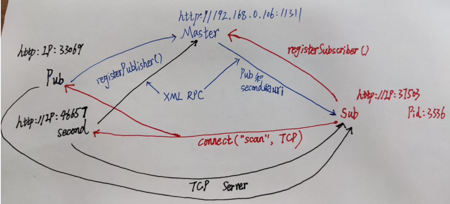
说的有点乱了,整个过程示意图如下:

节点退出问题
以前我的SIGINT回调函数是这样写的:1
2ros::shutdown();
ros::waitForShutdown();
这是从网上看来的,后来发现偶尔会很长时间才执行成功,甚至不能成功,一直阻塞。现在来看一下源码:1
2
3
4
5
6
7
8
9
10
11
12void waitForShutdown() // Wait for this node to be shutdown
{
while (ok())
{
WallDuration(0.05).sleep(); // 0.05s
}
}
bool ok()
{
return g_ok;
}waitForShutdown表示如果节点ok(),会一直睡眠。只有在ros::shutdown()的最后执行了g_ok = false;,有时一直无法退出,说明节点是一直ok(),因为节点在回调函数运行时无法完成shutdown,没执行到g_ok = false;