onInitialize
从参数服务器加载参数,并调用matchSize函数,根据主地图的参数来设置障碍层地图。
依据track_unknown_space参数,对代价地图取不同的默认值:1
2
3
4if (track_unknown_space)
default_value_ = NO_INFORMATION;
else
default_value_ = FREE_SPACE;expected_update_rate参数
将topics_string记录的观测源逐个输出到source字符串,并找到对应每个观测源的参数。
为每个观测源创建一个buffer,并将其指针存放进observation_buffers_中进行管理。并根据标志位确定是否将其添加到marking_buffers(标记障碍的观测数据) 与 clearing_buffers(用于清除小车与障碍间cost的观测数据):1
2
3
4
5
6
7
8
9
10
11
12// create an observation buffer
observation_buffers_.push_back(
boost::shared_ptr < ObservationBuffer>(new ObservationBuffer(topic, observation_keep_time, expected_update_rate, min_obstacle_height, max_obstacle_height,
obstacle_range, raytrace_range, *tf_, global_frame_,
sensor_frame, transform_tolerance) ) );
// check if we'll add this buffer to our marking observation buffers
if (marking)
marking_buffers_.push_back(observation_buffers_.back());
// check if we'll also add this buffer to our clearing observation buffers
if (clearing)
clearing_buffers_.push_back(observation_buffers_.back());
然后分别针对不同的sensor类型(LaserScan、PointCloud、PointCloud2)注册不同的回调函数,相应的订阅者和filter还要插入相应的容器1
2
3
4
5
6
7
8
9
10
11
12
13
14
15
16
17
18if (data_type == "LaserScan")
......
else if (data_type == "PointCloud")
......
else // PointCloud2
{
boost::shared_ptr < message_filters::Subscriber<sensor_msgs::PointCloud2>
> sub(new message_filters::Subscriber<sensor_msgs::PointCloud2>(g_nh, topic, 50));
if (inf_is_valid)
ROS_WARN("obstacle_layer: inf_is_valid option is not applicable to PointCloud observations.");
boost::shared_ptr < tf::MessageFilter<sensor_msgs::PointCloud2>
> filter(new tf::MessageFilter<sensor_msgs::PointCloud2>(*sub, *tf_, global_frame_, 50) );
filter->registerCallback(
boost::bind(&ObstacleLayer::pointCloud2Callback, this, _1, observation_buffers_.back() ) );
observation_subscribers_.push_back(sub); // 传感器数据订阅者
observation_notifiers_.push_back(filter); // 保证变换可行
}ObservationBuffer类是专门用于存储观测数据的类,它是ObstacleLayer的类成员。这里关注一下它的bufferCloud函数
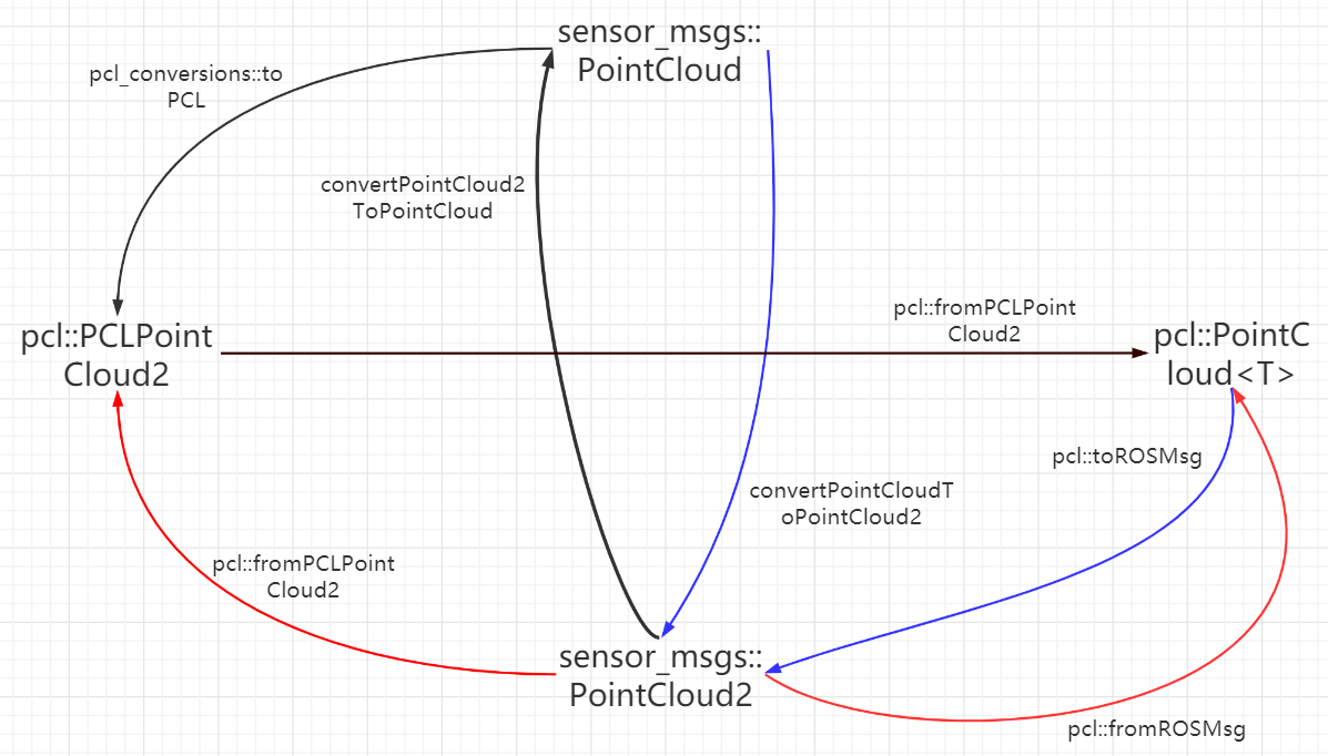
对三种传感器数据,都是先将收到的message转换为sensor_msgs::PointCloud2,再调用ObservationBuffer::bufferCloud,将点云数据存到buffer中,它实际又把点云消息转换为pcl::PointCloud < pcl::PointXYZ >格式后,再调用bufferCloud的重载函数。
| 这就是一个巨大的缺陷,深度相机和雷达获取的障碍都按PointCloud2类型放到buffer中,对两种障碍只能用同样的costmap参数,比如膨胀半径,影响了导航的调试 |
ObstacleLayer::pointCloud2Callback
1 | void ObstacleLayer::pointCloud2Callback(const sensor_msgs::PointCloud2ConstPtr& message, |
bufferCloud
非常重要的observation_list_就是在这里赋值的1
2
3
4
5
6
7
8
9
10
11
12
13
14
15
16
17
18
19
20
21
22
23
24
25
26
27
28
29
30
31
32
33
34
35
36
37
38
39
40
41
42
43
44
45
46
47
48
49
50
51
52
53
54
55
56
57
58
59
60
61
62
63
64
65
66
67
68
69
70
71
72
73
74
75
76
77
78
79
80void ObservationBuffer::bufferCloud(const pcl::PointCloud<pcl::PointXYZ>& cloud)
{
Stamped < tf::Vector3 > global_origin;
// std::list<Observation> observation_list_;
// create a new observation on the list to be populated
observation_list_.push_front(Observation());
// check whether the origin frame has been set explicitly or
// whether we should get it from the cloud
// yaml里可以不设置sensor_frame,在这里取点云的坐标系名称
string origin_frame = sensor_frame_ == "" ? cloud.header.frame_id : sensor_frame_;
try
{
// given these observations come from sensors, we store the origin pt of the sensor
Stamped < tf::Vector3 > local_origin(tf::Vector3(0, 0, 0),
pcl_conversions::fromPCL(cloud.header).stamp, origin_frame);
// global_frame_ 来源是obstacle_layer.cpp 中的 layered_costmap_->getGlobalFrameID();
// 转换 global_frame_ 和 origin_frame坐标系
tf_.waitForTransform(global_frame_, local_origin.frame_id_,
local_origin.stamp_, ros::Duration(0.5) );
// local_origin 转换到 global_frame_坐标系,变成global_origin
tf_.transformPoint(global_frame_, local_origin, global_origin);
observation_list_.front().origin_.x = global_origin.getX();
observation_list_.front().origin_.y = global_origin.getY();
observation_list_.front().origin_.z = global_origin.getZ();
// pass on the raytrace/obstacle range of the observation buffer to the observations
observation_list_.front().raytrace_range_ = raytrace_range_;
observation_list_.front().obstacle_range_ = obstacle_range_;
pcl::PointCloud < pcl::PointXYZ > global_frame_cloud;
// 把参数 cloud 转到global_frame_坐标系
pcl_ros::transformPointCloud(global_frame_, cloud, global_frame_cloud, tf_);
global_frame_cloud.header.stamp = cloud.header.stamp;
// now we need to remove observations from the cloud that are
// below or above our height thresholds
// 新的变量 observation_cloud,指向observation_list_的成员 cloud_
pcl::PointCloud < pcl::PointXYZ > &observation_cloud = *(observation_list_.front().cloud_);
unsigned int cloud_size = global_frame_cloud.points.size();
observation_cloud.points.resize(cloud_size);
unsigned int point_count = 0;
// copy over the points that are within our height bounds
// 从 global_frame_cloud中取出符合 z坐标的点,放到 observation_cloud
for (unsigned int i = 0; i < cloud_size; ++i)
{
if (global_frame_cloud.points[i].z <= max_obstacle_height_
&& global_frame_cloud.points[i].z >= min_obstacle_height_)
{
observation_cloud.points[point_count++] = global_frame_cloud.points[i];
}
}
// resize the cloud for the number of legal points
observation_cloud.points.resize(point_count);
// 时间戳和坐标系也复制过来
observation_cloud.header.stamp = cloud.header.stamp;
observation_cloud.header.frame_id = global_frame_cloud.header.frame_id;
}
catch (TransformException& ex)
{
// if an exception occurs, we need to remove the empty observation from the list
observation_list_.pop_front();
ROS_ERROR("TF Exception that should never happen for sensor frame: %s,
cloud frame: %s, %s", sensor_frame_.c_str(),
cloud.header.frame_id.c_str(), ex.what());
return;
}
// if the update was successful, we want to update the last updated time
last_updated_ = ros::Time::now();
// remove any stale observations from the list
purgeStaleObservations();
}